Control Valves Should Always Be in What Position
Control valves are subject to a number of common problems. It could be normally open or close and usually NO valve failure position is.
An Introduction To Control Valve Flow Control Technology Valve
When there is more than one valve position to be optimized such.
. ISA shows 45 degrees from vertical as acceptable and shows a fabricated support to absorb the weight of the actuator for valves with horizontal stems. At 50 both cooling valves are closed and the heating valve just starts to. Condensate passing through the steam control valves always has negative effect on the valve life.
Note that the flow balancing effect of the valve is the same in either case so there is no. At 25 the chilled water valve is closed but the regular cooling water valve is still fully open. Within an open-center position on a three-position four-way directional control valve what is all connected.
In case of power loss or air failure control valve should move in safe. The ISA handbook of control valves shows automated globe control valves mounted vertically as favored position. In designing a processing facility we usually use control valve to manipulates the temperature pressure level or fluid flow rate in process system.
A fail safety status is how the valve should operate when there is a loss of power or signal. Normal operation of the pool requires this valve to stay closed. Prevents heat buildup and inefficiency in the system The open-center position allows fluid to return to the reservoir when the system is idle which does what.
In vertical piping the easiest thing to do is replace the swing check or double door valve with an inline axial flow-style check valve. In each figure the coil pressure drop is 20 ft. X43H Strainer CLA-VAL 94-01 Combination Pressure Reducing Surge Control Valve On-Off Remote Control Valves Zone A Reduced Pressure Zone B Reduced.
The center position is commonly referred to as the first position. From left to right they are SPA MAIN DRAIN CLEANER SKIMMER and POOL MAIN DRAIN. The cascade temperature loop operates in a split-range fashion so that at a temperature controller TC output of 0 the cooling is maximum both chilled and cooling water valves are fully open.
The valves fail position is a safety precaution that protects your process in emergency situations. However axial flow check valves perform well in vertical piping locations. However the preferred installation is in horizontal pipeline with the actuator in a vertical position.
Figure 17-15 is the schematic for the center or neutral position of three-position directional control valves. Valve Positioning The control valve should always be installed on a horizontal steam line never vertically. The pump should always run above the minimum flow hence the control valve on the minimum flow line shall have fail safe position as Open.
It will not have an impact as the pump might also trip during the ESD. A control valve in a vertical installation has no ability to eliminate the buildup of condensate prior to the inlet of the control valve. The positions are shown as left activation center and right.
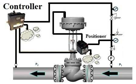
Flow balance valves placed on the return side will result in higher water pressures within the coil which means that more air will remain in the solution and out of the coil see Figures 1 and 2. The basic components of a valve position control strategy are illustrated as shown below. Selecting a Control Valve Selection of a control valve is primarily dependent upon on the service conditions and load characteristics of the application.
A control valve in a vertical installation has no ability to eliminate the buildup of condensate prior to the inlet of the control valve. S CV Speed Control Opening V X101 Valve Position Indicator Y X43 Y Strainer The closing speed control optional on this valve should always be open at least three 3 turns off its seat. Install the control valve preferably in a straight run of pipe away from bends or sections of abnormal velocity.
Actuator 910 Series Pneumatic The Trerice 910 Series Control Valve is designed for accurate performance within light industrial HVAC and commercial process applications. It depends on the process loop design. However we can install control valve in other position.
Each having its own consequences and safety effects. The valve should NOT oscillate or hunt at any of the step positions of the Slow Ramp. A pneumatic actuator applies force as a function of air pressure and pistondiaphragm area F.
The selection of control valve which is air-to-open or air-to-close is base on safety consideration. Set the gain of the valve controller to a point that gives the best response between these two conditions. VALVE POSITIONING The control valve should always be installed on a horizontal steam line never vertically.
Looking at the figure above each one of the valves is 3 position 4 way. If flow is going downwards a swing check valve will always be open and not doing its job. Special attention should be given to the type of center position that is used in a hydraulic control valve.
Fail-Safe Position Selection of Control Valve. Valve position control is a straightforward concept that may be easily implemented in most modern control systems. These are 3-way style valves.
Control valves are mechanical devices with moving parts and as such they are subject to friction primarily between the valve stem and the stem packing. 4 Control valves can be installed in any orientation. Valve position control may be used to achieve this type of regulation of the small and large valve.
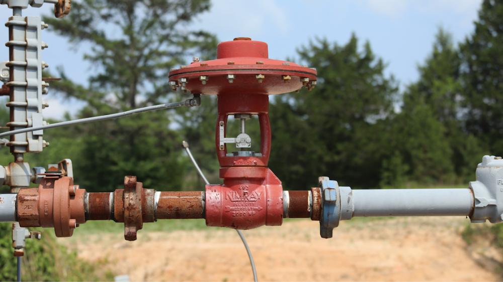
Condensate passing through the steam control valves always has negative effect on the valve life. Control valves can work in any orientationhowever the preferred installation is with actuator in vertical positionThis will prevent side loading of the internal componentsthe valve will have a much longer service life and maintenance easierHowever a special attention must be paid to the following aspects whenever the horizontal installation is provided. It is important to remember that valves are generally.
If you have a two or three position valve the first position will be the resting position. Revert in case of any query. For the cleaner to operate at maximum efficiency only the skimmer and cleaner valves should be open.
Manufacturers specific instructions should always be consulted for proper and appropriate valve positioner testing. The valve also should not be sluggish. Control valves should always be in what position.
There are a few different fail scenarios. This section is dedicated to an exploration of the more common control valve problems and potential remedies. The ability to handle abnormal conditions by directional velocity limits feedforward and adaptive tuning is greater for these applications because in most cases valves are being pushed to be as far open or closed as possible without interfering with the ability of the primary PID to provide tight control.
When Type 2 3 and 6 see Figure 17-15 are used the upstream side of the valve must have a relief or bypass valve installed. In the photo below there are four valves. The reason why a pneumatic control valves stem position corresponds linearly to the amount of air pressure applied to the actuator is because mechanical springs tend to follow Hookes Law where the amount of spring motion x is directly proportional to applied force F k x.
Control Valves Flow Characteristics

Basic Parts Of Control Valves Tpcontrol
7 Control Valve Installation Best Practices Kimray


Comments
Post a Comment